


Lithium batteries - Evaluation - Detection method for battery short circuit caused by electrode burrs
Jul,26,24
The author of this article analyzes the causes of zero voltage, with a focus on the phenomenon of electrode burrs causing zero voltage in batteries,
in order to accurately identify the cause of short circuits, solve this problem accurately,
and better understand the importance of controlling electrode burrs in the production process.
1 Experiment
1.1 Battery preparation
The experimental battery uses nickel cobalt manganese oxide lithium material (NCM111) as the positive electrode active material.
Mix the positive electrode active material, conductive agent SP, binder PVDF, and solvent NMP in a mass ratio of 66:2:2:30 to prepare a slurry,
which is coated on a 15 μ m thick carbon coated aluminum foil with a single-sided coating amount of 270g/m2.
Place the positive electrode sheet in an oven at a temperature of (120 ± 3) ℃, dry for 24 hours, and after rolling, the compacted density of the electrode sheet is 3.28g/cm3.
Using lithium titanate material (Li4Ti5O12) as the negative electrode active material.
Mix the negative electrode active material, conductive agent SP, binder PVDF,
and solvent NMP in a mass ratio of 52:2:2:44 to prepare a slurry, which is coated on a 15 μ m thick carbon coated aluminum foil with a single-sided coating amount of 214g/m2.
Place the negative electrode in an oven at a temperature of (110 ± 3) ℃ and dry for 24 hours.
After rolling, the compacted density of the electrode is 1.85g/cm3. After cutting the dried polarizer, the width of the polarizer is 136 0 ± 1.0) mm, with burrs on the pole piece not exceeding 12 μ m.
A 66160 type battery was prepared using 1mol/L LiPF6/EC+EMC+DMC (volume ratio 1:1:1) as the electrolyte and a 20 μ m thick PE porous separator as the separator, with a designed capacity of 45Ah.
After winding and assembling, weld the aluminum shell top cover, place the experimental battery in an oven at a temperature of (85 ± 3) ℃, dry for 24 hours, and then inject 200g of liquid into the battery cells.
After injection, the battery was left to stand at room temperature for 72 hours. After the standing, all experimental batteries were subjected to open circuit voltage (OCV) testing,
and the internal resistance and voltage of the batteries were recorded.
1.2 Charging Test
Perform internal resistance and voltage analysis using an AC internal resistance tester. Perform charging performance testing using a 5V-50A high-precision battery performance testing system.
When conducting a voltage test on a battery that has been left to stand after injection, if the voltage of the short-circuit battery is 0,
it is considered a zero voltage battery. Perform charging tests on zero voltage batteries.
Charge the battery with different currents such as 1A, 2A, and 3A at an ambient temperature of (25 ± 3) ℃. After charging, observe the changes in battery voltage.
Conduct experiments according to the increasing current and decreasing time, with charging times set to 5s, 10s, and 25s respectively.
1.3 Self discharge test
The anime tester is used to analyze the burrs of the electrode piece.
Perform internal resistance and voltage analysis using an AC internal resistance tester.
Use a 5V-50A high-precision battery performance testing system to test electrical performance. Use a high-temperature chamber to control the battery temperature.
The zero voltage battery before formation, after charging, the burrs melt and zero voltage no longer appears.
Perform a normalization process test on the battery, and the formation process is as follows:
① After the temperature in the high-temperature chamber reaches 120 ℃, let it sit for 120 minutes;
② After charging at 1.0C constant current to a cut-off voltage of 2.8V, switch to constant voltage charging, with a charging cut-off time of 2 hours;
③ Let it sit for 10 minutes;
④ After discharging at a constant current of 1.0C to a cut-off voltage of 1.5V, switch to constant voltage discharge, with a discharge cut-off time of 2 hours;
⑤ Let it sit for 10 minutes;
⑥ Repeat steps 2 to 5 3 times;
⑦ Charge at 1.0C constant current for 0.7h, then charge at 2.3V constant voltage with a cut-off current of 0.45A.
Perform self discharge testing on the battery after formation.
The method of testing static voltage shall be adopted, and the duration of voltage testing shall not be less than two months. After leaving the battery at room temperature (25 ± 5) ℃ for 24 hours,
conduct an open circuit voltage test and record it. Continue to let the battery stand at room temperature, and after one or two months, conduct another open circuit voltage test and record it.
2 Results and Discussion
2.1 Comparison of battery voltage before formation
The battery voltage during and after the charging process of 1A and 2A is shown in Figure 1.
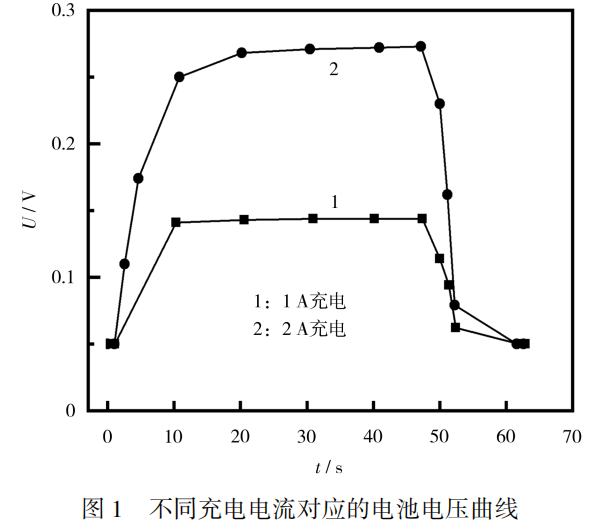
From Figure 1, it can be seen that the zero voltage battery can be approximated as having internal burrs and short circuits.
This battery can withstand a test with a current of 2A or less within 1 minute.
When the charging current is 1A or 2A, due to the presence of internal burrs causing a short circuit, the voltage reaches a stable value and no longer changes;
After stopping charging, the voltage quickly returns to 0.
Continue to increase the charging current, change the charging current to 3A, and set the charging time to 5s, 10s, and 25s respectively.
The charging test curve of the battery is shown in Figure 2.
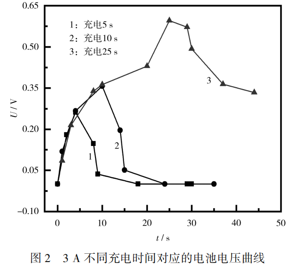
From Figure 2, it can be seen that when the charging current reaches 3A, the voltage state of the battery is similar to 1A and 2A charging at 5s and 10s charging times.
Continue to extend the charging time, and when the charging time exceeds 10 seconds, the voltage slowly rises;
When the charging time reaches 20 seconds, the voltage rises rapidly. After the charging stops, the voltage slowly drops, and there is no previous zero voltage phenomenon in a short period of time.
From the speed of voltage changes during the charging process, it can be inferred that the burrs inside the battery have melted due to the heat generated during charging.
Before the burr melts, there is a slow rise in voltage within 10-20 seconds after charging begins. After 20 seconds, the burr melts and the battery voltage rises rapidly.
After stopping charging, the battery voltage slowly decreases. After the burr melts, metal impurities still remain inside the battery, resulting in faster self discharge than normal batteries.
After normalizing the battery, test the self discharge speed.
2.2 Comparison of self discharge of batteries after formation
The batteries selected for the experiment were charged and discharged according to the 1.3 formation process. After step ⑦, the state of charge (SOC) of the battery was about 80%.
Perform self discharge testing on the battery at room temperature, and compare it with normal batteries and batteries containing impurities from the same batch. The test data is shown in Table 1.
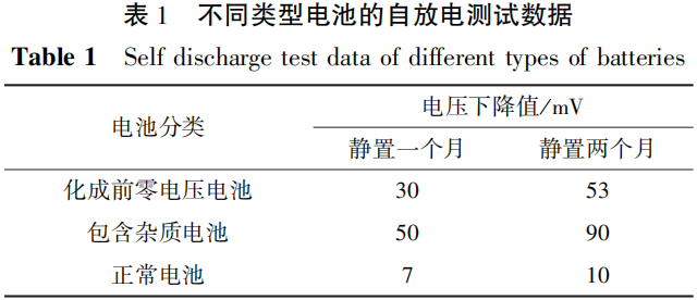
From Table 1, it can be seen that the phenomenon of battery self discharge caused by burrs does exist, which affects the battery's charge retention ability.
By analyzing the reasons for abnormal self discharge using charging current, the abnormal situation of burrs on the electrode pieces during the manufacturing process can be intuitively reflected,
indicating that further process control requirements should be strengthened, cutting tools should be maintained in a timely manner, battery performance should be ensured,
and safety hazards should be reduced in the production process. After the burr melts, there are still metal impurities inside the pole piece. After measuring the self discharge data of the battery after capacity division,
it can be seen that the voltage of a normal battery drops by about 7mV after being left at room temperature for one month, and by about 10mV after two months,
indicating that the self discharge rate of a battery with excessive burrs is higher than that of a normal battery. Based on the analysis of the voltage before formation and the self discharge data after capacity division,
it can be concluded that excessive burrs will lead to abnormal charge retention performance of the battery.
The burrs on the battery electrodes will not completely disappear and will have a long-term impact on the performance of the battery.
3 Conclusion
During the battery manufacturing process, controlling the size of electrode burrs is a key parameter. After the burr causes a short circuit, the voltage of the battery after injection is 0.
Charging short-circuit batteries caused by burrs with low current will result in a constant voltage.
When the current reaches the burr melting value, there are metal impurities inside the battery, which will continue to affect the self discharge of the battery,
and the self discharge rate is higher than that of normal batteries. This method can identify battery short circuits caused by burrs during the battery manufacturing process,
thereby guiding the strengthening of the inspection of cutting, die-cutting, and winding equipment in the battery production process, and avoiding the production of large quantities of unqualified batteries.


