


Analysis and Countermeasures of Lithium Evolution in Negative Electrode of Lithium Batteries!
Aug,05,24
1. Mechanism of lithium deposition on negative electrode
1.1 Formation conditions for lithium deposition on negative electrodes
The lithium insertion potential of graphite is 65~200mV (vs. Li+/Li0).
When the potential of the negative electrode is close to or lower than the precipitation potential of metallic lithium,
lithium ions precipitate on the surface of the negative electrode in the form of lithium metal.
The experiment found that the precipitation reaction of lithium ions on the negative electrode surface and the insertion reaction in graphite occur simultaneously.
During the charging process, a portion of lithium ions deposit on the negative electrode surface in the form of lithium metal,
while the remaining lithium ions are embedded in graphite; During the discharge process, ion deintercalation and deposition of lithium metal detachment occur.
During the stripping process of lithium metal, there will be the formation of "dead lithium".
The reaction between dead lithium and electrolyte is the main cause of capacity loss and shortened cycle life in lithium-ion batteries.
Negative lithium deposition is the result of charge transfer restriction (CTL) and solid-phase diffusion restriction (SDL).
As charging progresses, the positions where lithium ions can be embedded between graphite layers gradually decrease, limiting the diffusion of lithium ions in the graphite solid phase,
and the corresponding lithium insertion current also gradually decreases;
Meanwhile, due to the much faster diffusion rate of lithium ions from the electrolyte to the negative electrode than their embedding rate in graphite,
more and more lithium ions are accumulating on the surface of graphite,
driving the negative electrode potential to approach the lithium deposition potential, resulting in lithium deposition on the negative electrode.
1.2 Chemical reaction of lithium deposition on negative electrode
During the process of lithium-ion charging, if metallic lithium precipitates on the surface of the graphite negative electrode, the following four chemical reactions will occur:
(1) Lithium insertion reaction:
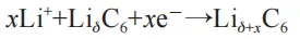
(2) The precipitation reaction of lithium metal:
(3) The reaction between precipitated lithium and unsaturated graphite forms reversible lithium:
(4) The reduction reaction between the precipitated metallic lithium and the electrolyte solvent forms a solid electrolyte membrane (SEI membrane), which forms irreversible lithium:
Distribution state of lithium deposition on negative electrode 2
Negative electrode lithium deposition can be divided into edge lithium deposition, local lithium deposition, and uniform lithium deposition according to their distribution state.
2.1 Edge lithium deposition
In the design process of lithium-ion batteries, for safety reasons and to prevent lithium deposition from the negative electrode,
the area of the negative electrode sheet is larger than that of the positive electrode sheet, that is,
the edge of the negative electrode sheet exceeds the size of the positive electrode sheet by 1-3mm,
and the area where the negative electrode sheet protrudes from the positive electrode sheet is called the overhang (Figure 1).
There are two reasons for lithium deposition at the edge:
firstly, the design of the overhang is too large, causing an excess of lithium ions at the edge of the positive electrode,
resulting in the inability to embed excessive lithium ions from the positive electrode in the overhang area of the negative electrode during charging, leading to lithium deposition;
The second issue is the mismatch in surface density caused by the thick edge effect during the coating process of the positive and negative electrode plates.
For example, if the surface density of the positive electrode edge is too high or the surface density of the negative electrode edge is too low, it can cause lithium deposition.
picture
2.2 Localized lithium deposition
The distribution of localized lithium deposition is relatively random, with no fixed area and a discontinuous spot like distribution.
The main reasons for local lithium deposition are:
external forces on the battery cell (such as compression, cell deformation, etc.), local defects in the electrode plate, and local defects in the diaphragm.
In addition, insufficient wetting of the electrolyte, residual gases in the separator and negative electrode can also cause lithium deposition during the negative electrode charging process.
2.3 Uniform lithium deposition
Uniform lithium deposition refers to the uniform coverage of lithium metal on the entire surface of the negative electrode.
The uniform lithium deposition is related to the uniformity of current distribution during the charging process,
and the uniformity of current distribution is related to the quality of the electrode,
such as pore distribution, tortuosity, surface morphology, conductive network, etc; In addition,
the uniformity of current distribution is also affected by the position and quantity of the electrode ears.
3 Factors affecting lithium deposition in negative electrodes
3.1 Change in N/P value
The N/P value is the ratio of the negative electrode capacity to the positive electrode capacity in lithium-ion batteries, also known as the cell balance (CB) value.
Its calculation formula is as follows:
In the formula: q is the specific capacity of the active material, mAh/g; m is the mass of the active material, g.
The N/P value is an important factor affecting battery safety.
A lower N/P value will cause the negative electrode to reach the lithium deposition potential, leading to lithium deposition during the charging process.
On the other hand, although a higher N/P value can suppress lithium deposition at a given cut-off voltage,
it can lead to excessive lithium removal from the positive electrode,
causing not only instability of the positive electrode crystal structure but also oxidation reaction of the electrolyte at the positive electrode.
During the use of batteries, the N/P value is constantly changing, and its variation is related to factors such as battery charging rate, cut-off voltage, ambient temperature,
and number of cycles. For example, Mao et al.'s research results showed that when the negative electrode charging rate exceeded 1C,
the capacity rapidly declined, while the positive electrode capacity showed a smaller decline.
When the charging rate increased from 1/10C to 4C, under low rate 1/10C charging conditions, the N/P value was 1.15.
When the charging rate increased to 3C and 4C, the N/P value decreased to 1.0 and 0.5, respectively, and severe lithium deposition occurred in the negative electrode.
In addition, the change in N/P value is related to the chemical system of the battery.
For example, high nickel positive electrode materials generally have higher N/P values with increasing cycle times due to structural collapse and metal ion dissolution;
For silicon-based negative electrode materials, the large volume expansion, delamination, particle rupture, and iterative formation of SEI can lead to a decrease in N/P value.
In summary, there are many factors that affect the variation of N/P values, such as the type of positive and negative electrode active materials, charging rate, charging and discharging cut-off voltage, etc.
Therefore, in the battery design process, it is necessary to consider the characteristics of N/P value variation to avoid negative electrode lithium deposition caused by a decrease in N/P value.
3.2 Low temperature charging
From thermodynamic analysis, as the ambient temperature decreases, the charge transfer impedance increases, and the negative electrode potential decreases.
When it reaches the lithium deposition potential, lithium ions precipitate on the negative electrode surface in the form of metallic lithium.
From a dynamic analysis, according to Arrhenius' law, as the temperature decreases, the chemical reaction rate decreases.
When the charging temperature decreases, the diffusion rate of lithium ions in the electrolyte, SEI film, and graphite solid phase will also decrease.
With the energy barrier unchanged, the probability of lithium insertion reaction decreases,
and a large number of lithium ions obtain electrons at the negative electrode and undergo lithium precipitation.
Therefore, when lithium-ion batteries are used under low temperature conditions,
it is necessary to reduce the electrode polarization impedance, improve the diffusion rate of lithium ions in the electrolyte, SEI film, and graphite solid phase,
and avoid lithium deposition in the negative electrode.
3.3 Fast Charging
When charging at high speed, the electrode surface has a higher current density per unit area, that is, a higher concentration of lithium ions.
The driving force for lithium ions to embed into the solid phase from the graphite negative electrode surface is the concentration gradient.
When the lithium ion transport speed is slow (low temperature, high charge state,
or material with high energy barrier) and the current density is relatively high during the charging process, lithium deposition will occur;
In addition, high rate charging can also promote the negative electrode to reach the lithium deposition potential, resulting in lithium deposition.
Therefore, under low state of charge (SOC), when charging the battery at a high rate, as the SOC increases, low current charging is used to avoid lithium precipitation;
Under low temperature conditions, the lithium-ion battery should be charged with a small current.
After charging, let it stand for a certain period of time, and the precipitated metallic lithium will re embed into the graphite crystal, reducing the loss of active lithium.
3.4 Overcharging
Overcharging refers to the behavior of continuing to charge a battery when the charging voltage exceeds the upper cut-off voltage after it is fully charged.
The degree of overcharging of lithium-ion batteries is generally represented by the SOC of the battery. The degree of lithium deposition at different SOC is shown in Figure 2.
When the SOC exceeds 185%, the negative electrode surface is completely covered by metallic lithium.
For power batteries, individual cells need to be connected in series and parallel before use.
If the voltage, internal resistance, and capacity consistency of each individual cell is poor,
it is easy to cause overcharging of individual cells, leading to lithium deposition on the negative electrode surface and causing safety accidents.
picture
There are two ways to control the overcharging problem of lithium-ion batteries:
(1) Control through battery management system;
(2) Internally, by increasing the oxidation potential of the electrolyte and raising the starting temperature of battery thermal runaway.
3.5 Overhang is too large
The existence of lithium ion outflow and inflow phenomena in the negative electrode active region and overshoot region is closely related to the capacity changes of the battery and the lithium deposition in the negative electrode. For example, during the charging process of a battery, due to the presence of an overhanging area, the negative electrode overhanging area is not completely lithiated when charging is completed, as shown in Figure 3 (a). A gradient distribution of lithium is formed at the edge of the negative electrode sheet, and during the subsequent static process, the lithium embedded in the negative electrode sheet diffuses from the center to the edge. As shown in Figure 3 (b), after discharge, there is still un deintercalated lithium in the overhanging area, indicating that during the discharge process, the positive electrode sheet edge not only receives lithium ions from the negative electrode area directly opposite its edge, but also receives lithium ions deintercalated from the negative electrode overhanging area. With the increase of circulation, the lithium concentration at the edge of the positive electrode sheet will become higher and higher, leading to the charging process, which is prone to... Lithium deposition occurs at the edge of the negative electrode. Therefore, under the quality of electrode manufacturing and the precision achievable by manufacturing equipment, it is advisable to design a smaller overhang area as much as possible to avoid lithium deposition.
4、Solution for lithium deposition on negative electrode
4.1 Battery structure optimization
The structure of the battery cell is closely related to the lithium deposition window of the negative electrode.
For example, reducing the overhang area can prevent edge lithium deposition caused by a large amount of lithium ions migrating from
the positive electrode edge to the negative electrode edge during the charging process.
By utilizing multi pole ear design, the distribution of cell current density during battery charging can be ensured,
avoiding local lithium deposition caused by excessive local current density.
In addition, a reasonable N/P value is also an effective measure to suppress lithium deposition in the negative electrode.
4.2 Quality control of polarizer
The manufacturing steps of polarizer include: slurry preparation, polarizer coating, and polarizer rolling.
These three steps affect the porosity, tortuosity, and surface density of the electrode, which in turn affects the current distribution during battery charging.
The influence of electrode plates (including positive and negative electrodes) on lithium deposition in negative electrodes is mainly manifested
in local lithium deposition caused by insufficient slurry stirring or electrode plate coating defects,
as well as large-area lithium deposition caused by insufficient lithium insertion kinetics in negative electrodes due to excessive compaction of electrode plates.
4.3 Surface treatment of polarizer
Avoiding lithium deposition on the negative electrode can be achieved by reducing the overpotential of the graphite negative electrode
and increasing the overpotential of lithium deposition on the negative electrode surface.
Lithium evolution belongs to the process of electrocrystallization, which first nucleates and then grows.
The driving force for growth is the difference in interfacial energy between the negative electrode surface and metallic lithium.
By depositing a nanoscale metal layer on the negative electrode surface through magnetron sputtering,
the overpotential of lithium metal precipitation can be increased and the driving force for lithium metal growth can be weakened, achieving the goal of improving lithium deposition.
In addition, constructing a pit array on the surface of the negative electrode by laser etching can effectively reduce the diffusion resistance and charge transfer impedance of lithium ions in low-temperature environments,
and reduce the risk of lithium deposition.
4.4 Optimization of Negative Electrode Materials
The lithium insertion kinetics of negative graphite can be described by energy barriers.
The energy barriers for lithium ions embedded into graphite crystals from the end face and plane are 0.3~0.7eV and 10eV, respectively.
Even if there are defects on the graphite basal plane, the energy barrier for lithium insertion on the basal plane is still one order of magnitude higher than that on the end face (2.36~6.35eV);
Therefore, lithium ions are more easily embedded between graphite layers from the end face.
Among them, the end faces of graphite are divided into two types of structures: arm chair edged and Z-shaped.
The study of boron (B) and nitrogen (N) doping on the arm chair and Z-shaped end faces respectively found that after B doping on the arm chair shaped end face,
the Fermi level decreased and the adsorption energy increased,
which is conducive to the improvement of lithium insertion kinetics of graphite.
Kim et al. improved the kinetics of graphite negative electrode by doping nickel on the end face of graphite material and depositing amorphous SiO2 coating on the surface, as shown in Figure 4.
End face doping can enhance mass transfer kinetics, and nickel metal particles can improve electronic conductivity.
After depositing a nano silicon layer on the surface, the potential of silicon lithium alloying can be increased (0.22V, vs. Li/Li+), which suppresses the negative electrode from reaching lithium deposition potential.
Other methods to enhance negative electrode kinetics include increasing the interlayer spacing of graphite and surface etching, each with its own characteristics.
Sometimes it is difficult to achieve the desired effect with a single plan, and multiple plans need to be combined and work together to achieve the goal of preventing lithium deposition.
4.5 Optimization of electrolyte additives
The negative electrode lithium deposition is influenced by negative electrode polarization and lithium insertion kinetics,
which are related to the mechanical properties, chemical stability, and ion conductivity of the SEI film.
Functional additives (film-forming agents) in the electrolyte can help improve the quality of the SEI film.
Therefore, developing suitable film-forming agents is also an effective way to solve the problem of negative electrode lithium deposition.
There are many types of film-forming additives,
such as unsaturated carbon containing compounds, sulfur-containing organic compounds, halogenated organic compounds, inorganic compounds, ionic compounds, and other organic compounds.
From the perspective of solving lithium deposition in negative electrodes,
optimizing electrolyte film-forming agents not only considers the structural stability of the film, fewer side reactions, and low impedance,
but also focuses on improving the ion conductivity of the film.
For example, the commonly used fluorinated vinyl carbonate (FEC) film-forming agent forms a structurally stable SEI film containing LiF on the negative electrode surface.
However, the SEI film of LiF has high impedance and low ionic conductivity.
By adding tris (trimethylsilyl) phosphate (TMSP) to the electrolyte,
the methylsilyl group in TMSP reacts with Lewis bases (fluoride, water, hydroxyl, methanol), avoiding side reactions of HF and electrolyte lithium salts,
and effectively improving the ionic conductivity of the SEI film.
Jones et al. added different electrolyte additives to the electrolyte and conducted low-temperature charging experiments.
The results showed that LiFSI had the best effect in inhibiting lithium deposition, with no lithium deposition at -30 ℃;
From the perspective of improving electrolyte kinetics, LiDFOB has the best effect, but lithium deposition is the most severe.
The reason is that the addition of LiDFOB enhances the kinetics of the positive electrode, resulting in relatively insufficient improvement in the kinetics of the negative electrode and causing lithium deposition.
Therefore, it is necessary to comprehensively consider the effects of additives on both the positive and negative electrodes.
4.6 Optimization of Charging Process
Adjusting the charging environment and designing the charging program based on the law of lithium deposition on the negative electrode is also an effective way to solve the problem of lithium deposition on the negative electrode.
4.6.1 Battery preheating technology
Yang et al. achieved self heating function of the battery by optimizing the cell structure [Figure 5 (a)].
Under 6C charging conditions, the battery without preheating lost 20% of its capacity after 60 cycles.
As the charging temperature increases, the battery cycle life significantly increases, and the amount of lithium metal deposited on the graphite electrode decreases.
At 60 ℃, a complete and clear morphology of graphite particles can be observed in scanning electron microscopy images.
Raising the battery temperature can improve the electrolyte conductivity, graphite negative electrode surface exchange current density,
and lithium ion solid-phase diffusion rate, solving the problem of lithium deposition in the negative electrode.
As shown in Figure 5 (b), when the temperature rises from 20 ℃ to 60 ℃, the exchange current density on the graphite surface increases by 13 times,
the solid-phase diffusion coefficient of graphite increases by 5.6 times, and the ion conductivity of the electrolyte increases by 1.9 times.
The above results fully demonstrate that the increase in charging temperature can significantly alleviate or even eliminate lithium deposition.
Figure 5: The structure of a self heating battery (a) and the effect of battery charging temperature changes on exchange current density, solid-phase diffusion rate, and electrolyte conductivity (b)
It should be noted that increasing the temperature has a positive effect on improving lithium deposition, but excessively high temperatures can cause the SEI film to grow faster, resulting in loss of active lithium.
Therefore, the use of self heating technology must ensure precise temperature control.
4.6.2 Charging Program Design
During the charging process, as the battery voltage continues to rise, the negative electrode potential gradually decreases.
When the negative electrode potential is lower than the lithium deposition potential, lithium deposition occurs.
Therefore, controlling the negative electrode potential above the lithium deposition potential can prevent the occurrence of lithium deposition.
Koleti et al. proposed a three-stage charging method [constant current charging (CC1) → constant voltage charging (CV) → CC2].
First, the battery voltage vtc at the time of negative pole lithium separation is determined by the voltage relaxation curve (VRP) method, and the cut-off voltage at the CC1 stage is set to vhcc end.
By adjusting the vhcc end value during the battery cycle until its value is equal to vtc,
it can ensure that the negative pole potential is higher than the lithium separation potential during the cycle, and no lithium separation occurs during the charging process.
The standard charging procedure includes CC and CV stages. In the CC stage, the negative electrode potential gradually decreases, and in the subsequent CV stage,
the negative electrode potential gradually increases.
Lithium deposition occurs in the CC stage.
By constructing three electrodes,
the voltage of the battery during lithium deposition can be determined to set the charging procedure and ensure that there is no lithium deposition during the charging process.
For example, high rate charging is used at low SOC, and when the negative electrode potential is about to reach the lithium deposition potential, it switches to CV charging.
This not only shortens the charging time but also avoids lithium deposition, which can be determined by constructing three electrodes.
5 Conclusion and Prospect
This article mainly discusses the mechanism of lithium deposition on the negative electrode of lithium-ion batteries,
analyzing the lithium deposition on the negative electrode from the microstructure to the macrostructure of the battery cell electrode,
from the usage conditions to the application environment of the battery.
Based on the mechanism and influencing factors of lithium deposition on negative electrodes,
some strategies for understanding and resolving lithium deposition are proposed. In the future, we can consider expanding from the following aspects:
(1) Optimization of battery structure, such as precise setting of N/P values, multi pole ear design of batteries, and combination of assembly methods such as winding and stacking;
(2) Improvements in manufacturing processes, such as increased precision of battery cell overhanging, improved consistency in electrode quality and thickness,
regulation of micro pores in electrode sheets, and changes in surface morphology;
(3) New material development, such as improving dynamic performance through coating and doping of graphite material surface and crystal structure;
By optimizing the design of electrolyte additives and solvents, the kinetics of the solid-liquid interface can be improved and SEI impedance can be controlled;
By adjusting the microporous structure of the membrane, the rate of lithium ion desolvation and the distribution of lithium ions at the electrode interface can be changed;
(4) Optimization of electrolyte additives, such as in-depth study of the film-forming mechanism of SEI film and the relationship between the structure and properties of SEI film,
quantification of characteristic parameters of SEI film, such as elastic modulus, fracture toughness,
and adhesion between SEI film and electrode surface, providing theoretical basis for the optimization of electrolyte additives;
(5) Optimization of charging programs, such as constructing a multi physics field model for lithium-ion batteries, conducting in-depth research on the mechanism of lithium deposition,
and providing scientific basis for setting charging parameters;
(6) The early quantitative diagnosis of lithium deposition is mostly achieved through offline or destructive testing methods.
If the diagnosis can be carried out in the early stage of lithium deposition and the charging and discharging procedures can be corrected in a timely manner to achieve closed-loop control,
it may be an effective means to solve lithium deposition in the future;
(7) Functional coating on the surface of the negative electrode,
which constructs a functional coating on the surface of the negative electrode,
reduces the impedance of the SEI film and increases the charging potential of the negative electrode surface, enhances the dynamic performance of the negative electrode,
expands the lithium deposition window of lithium-ion batteries, and prevents lithium deposition.
Previous: Lithium iron phosphate battery


